I recently managed to build a crude water-level controller for my overhead water tank at home (expect a post on how to build yours 🙂 ). Being a newbie, my platform of choice was of course, Arduino. When it came to installing the setup, though, I wanted just a micro-controller, and not a huge board with a USB port. Taking the easy way out, I decided to burn the Arduino bootloader on an ATMega8, and upload the code to it.
There is enough documentation on the internet to walk you through every step of the process. So, I will just summarize what worked for me, and provide links to the resources that helped.
To burn the bootloader, you need a programmer. The most sensible option seemed to be Usbasp. I didn't have one, so I used the Arduino as a programmer.
What I needed / used:
- An Arduino. I used a derivative called Roboduino, because that was all I could lay my hands on.
- An ATMega8.
- A crystal of appropriate frequency.[1]
- Two 22 pF capacitors.
- A 10 uF capacitor.
- A 10kΩ resistor.
- A breadboard.
- A few lengths of wire.
- A power supply. I cut off the connector at the end of a mobile phone travel adapter, and used it as a DC voltage source.
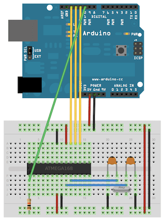
After uploading the ArduinoISP sketch, I connected a 10uF capacitor between RESET and GROUND (also denoted as GND) on the Arduino, because my board was more or less similar to the Arduino Uno.
How I wired it up:
I wired it up exactly as mentioned in the ArduinoISP tutorial. Here is the image for a quick reference.

The bootloader:
All that is left now is to actually burn the bootloader. To do this,
- Go to Tools > Programmer from the menu and select 'Arduino as ISP'.
- Go to Tools from the menu again, and click 'Burn Bootloader'.
The program:
Now load the program that you want to upload to the ATMega8, in the Arduino IDE. Go to File menu and click 'Upload using Programmer'.
Going solo:
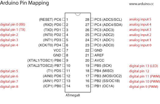
Now it is time for the ATMega8 to man up and deal with the task at hand :). Just remember that the pins on the Arduino do not translate to the corresponding pins on the ATMega8. You will have to search for “Arduino to <insert micro-controller name here> pin mapping” on Google to find out what the pins on the Arduino actually translate to. Here is what it looks like, for the ATMega8.

Provide an appropriate power supply, and wire up your circuit as per the pin mapping. I used the same stripped travel adapter for power. I connected pins 7 (VCC), 21 (AREF) and 20 (AVCC) to +5V and pins 8 and 22 to GND (Ground).
The troubles I ran into:
- avrdude: stk500_getsync(): not in sync: resp=0x00. Ah, the dreaded
not in sync! This can be due to a variety of reasons. Mine turned out to be the crystal. I used a 16MHz crystal with the ATMega, while the crystal on board the Roboduino was a 12MHz one. I replaced the 16MHz with a 12MHZ crystal, and that solved the problem. 🙂
Comments and corrections are welcome 🙂
Images are from the Arduino website, and are subject to copyright.
This post used to be a part of my old blog, and was migrated here for legacy reasons.
